CAD DIGITAL LOAD CELL
10-20-30t.
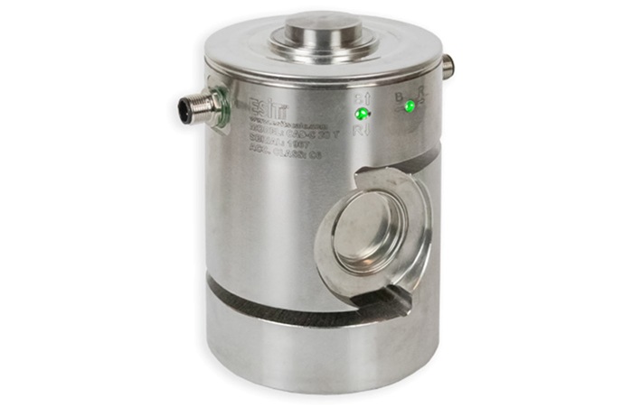
Model CAD has double sockets, cable connection is done by jumping from one load cell to another one. It does not require junction boxes, so it is very easy to change in case of fault.
Model CAD load cells are based on the shear force principle to measure forces in the compression direction. It has been developed for use in high capacity, electronic weight and force measurement applications in industrial environments. Thanks to its’ perfect and rugged body, it offers high resistance to side forces and overload conditions.
Stainless steel body is resistant to corrosion. CAD load cells are suitable for heavy industrial conditions and chemical environments. It finds applications in high-capacity vehicle scales, platform scales, tank weighing systems and process weighing applications.
When compared to other brand digital load cells, the most important advantage of CAD load cells is that they bear an electronic angle meter inside. With this feature, the technician is alerted by coloured LEDs for proper assembly during installation.
Main problem in truck scales is side forces. Platform elongation due to thermal expansion of temperature differences between summer and winter change and platform deformation due to load distribution causes errors in measurement. In both cases, the load cells which are placed perpendicular to the ground become athwart and may cause measurement error. With thanks to the patented angle compensation Technology of , vertical deflection angle of the load cell is detected via sensors to ensure an accurate weight measurement.
CAD load cell is 80% more resistant to side forces than other load cells working with column type principle. Particularly, the major
Features:
-
Certified to OIML R60 standards
-
Welded hermetic sealed body
-
100% resistant to side forces
-
300% resistant to overload
-
IP68 industrial protection
-
Lightning Protection
-
Installation angle compensation
-
RS485 communication
-
Automatic corner calibration from indicator
-
Measurement error detection
-
24-bit A/D converter
Technical specification:
|
Maximum capacities (Emax) |
t |
10, 20, 30 |
|
Accuracy class (OIML R 60) |
C3, C4, C5, C6 |
|
|
Maximum number of verification intervals |
3000, 4000, 5000, 6000 |
|
|
Minimum verification interval |
Emax/10000 Emax/20000 Emax/20000 Emax/40000 |
|
|
Combined error |
% |
≤±0.02, ≤±0.012, ≤±0.012, ≤±0.01 |
|
Creep error over 30 min.(DR) |
%Emax |
≤±0.0166 ≤±0.0125 ≤±0.0100 ≤±0.080 |
|
Maximum safe overload |
%Emax |
150 |
|
Maximum safe sideload |
%Emax |
100 |
|
Ultimate load |
%Emax |
300 |
|
Stretching |
mm |
≤ 0.3 |
|
Excitation voltage(Umax) |
V |
12-24 |
|
Excitation Current |
mA |
100 |
|
Output signal (at nominal load) |
Counting |
200 000 |
|
Analog/Digital converter (sigma delta) |
bit |
24 |
|
Analog/Digital converter speed |
Hz |
1 or 200 |
|
Asynchronous communication speed |
Baud |
115.200 |
|
Data interface |
Semi Duplex |
RS 485 |
|
Angle measurement error |
Degree |
0.1 |
|
Inclination angle error display |
2 pieces 3 coloured Led |
|
|
Insulation voltage |
V |
2500 |
|
Compensated temperature range |
°C |
-10...+40 |
|
Operating temperature range |
°C |
-40...+70 |
|
Load cell material |
Stainless Steel |
|
|
Sealing (EN60529) |
IP68 |
|
|
Weight |
kg |
8 |